
What is tolerance stack-up?
Engineering tolerances decide the acceptable range of sizes for a manufactured component. When manufacturing parts for an assembly, certain dimensions will contribute an error due to the variation in component size between the tolerance limits. As these errors build up, certain parts of the assembly will become misaligned or fit incorrectly and the system may not function as intended. This process is known as tolerance stack-up.
Engineering Example
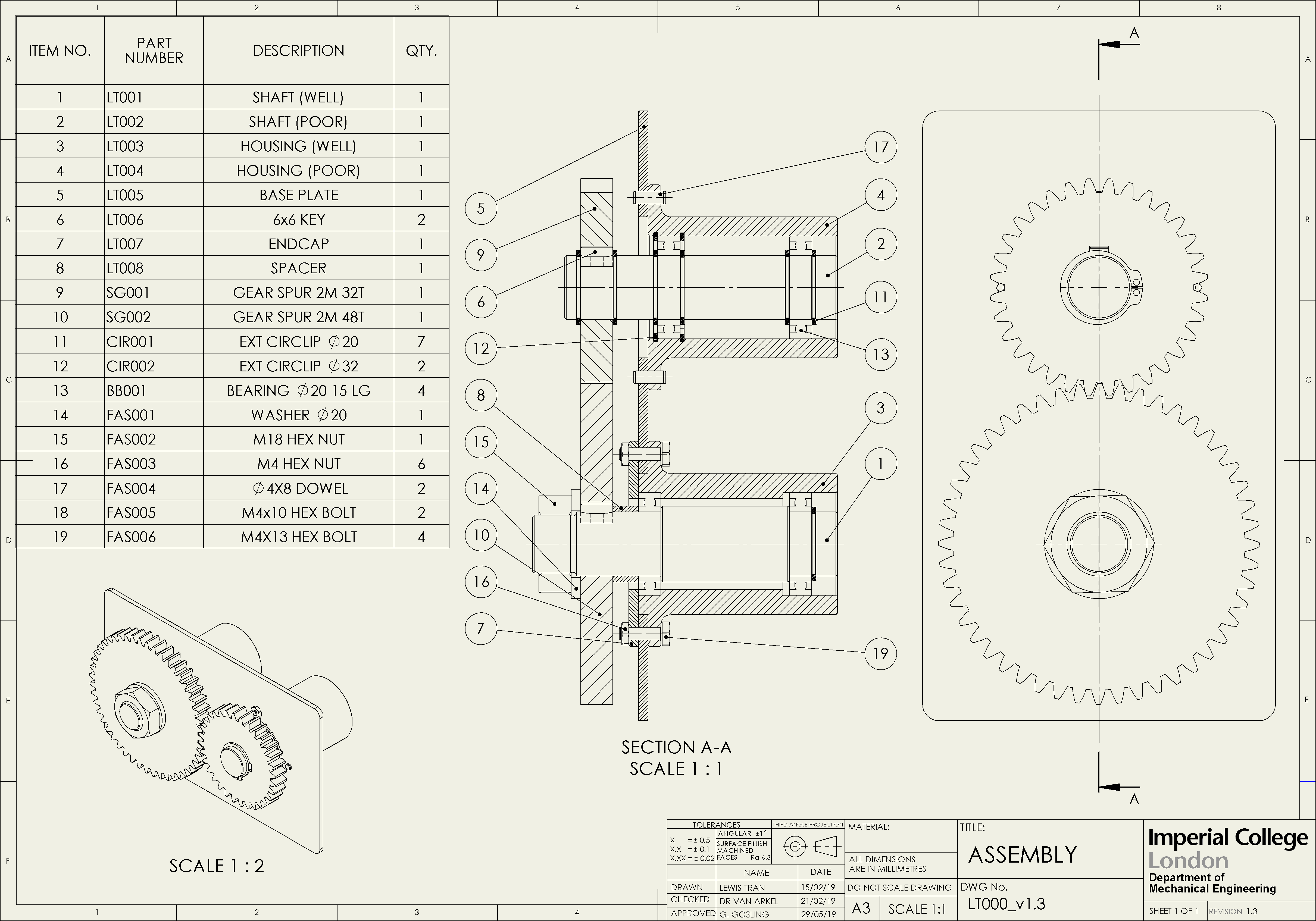
This Learning Object covers the design of a simple mechanism, made up of two shafts, two housings and a fixed plate (see Figure 1). In this example, one side of the mechanism (blue) is designed using different types of constraints to reduce tolerance stack-up and minimise misalignment of the gears. The other side (orange) is an example of a poorly designed assembly that experiences significant tolerance stack-up and is susceptible to severe misalignment.
Using this Learning Object
The aim of this Learning Object is to demonstrate how your design decisions can influence the final outcome of a manufactured product. The tabs in the top right corner will direct you to a set of engineering drawings, where you will be presented with examples of good and bad engineering design. Take the time to inspect these drawings, try out the interactive features and consider some of the discussion points. The simulation page can be used to simulate the tolerance stack of the gear mechanism as if it were to be manufactured on a mass scale. Reflect on the stack distribution and discuss how it relates to the two engineering design examples.
- Well Designed Shaft
- Poorly Designed Shaft
- Spacer
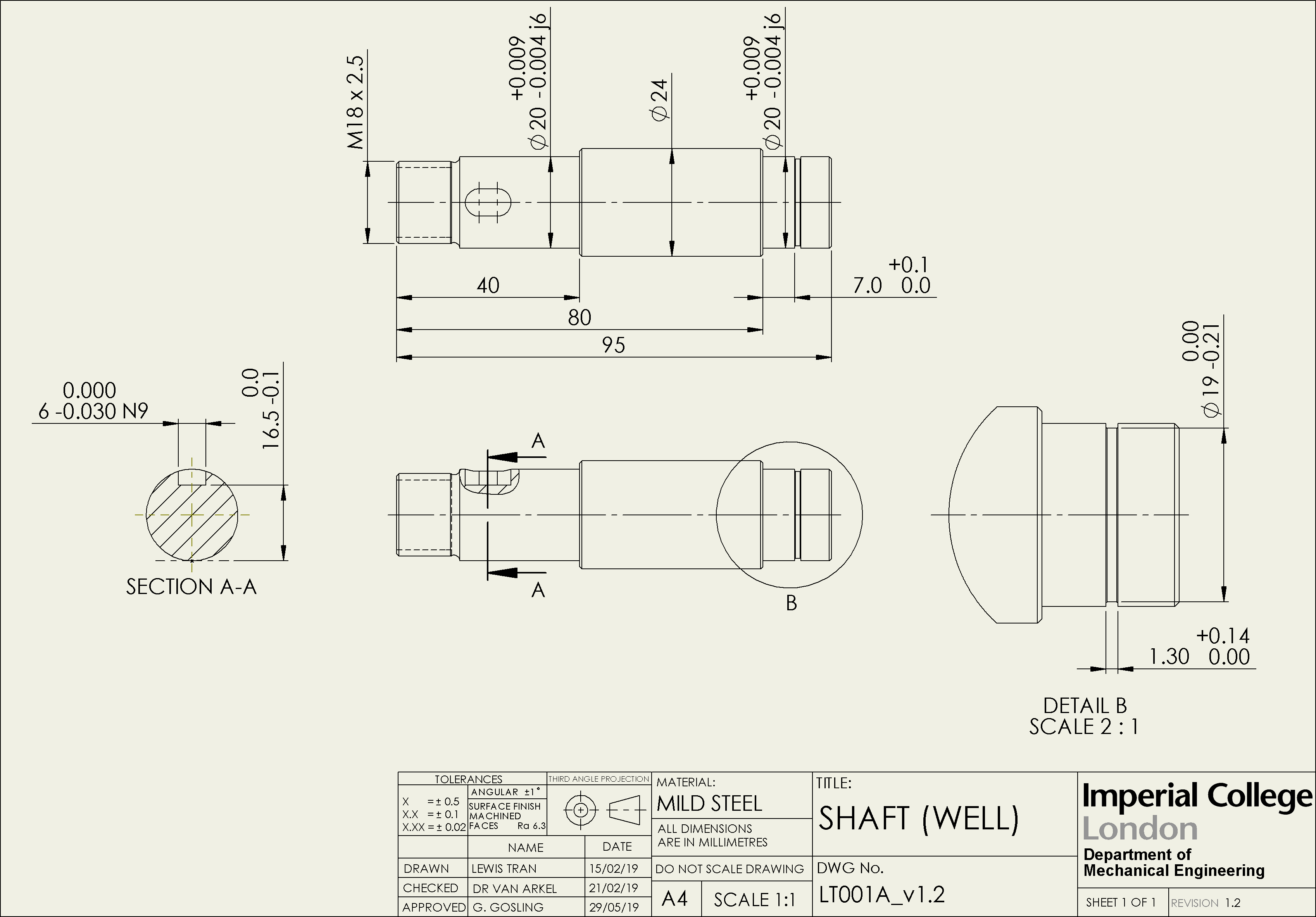
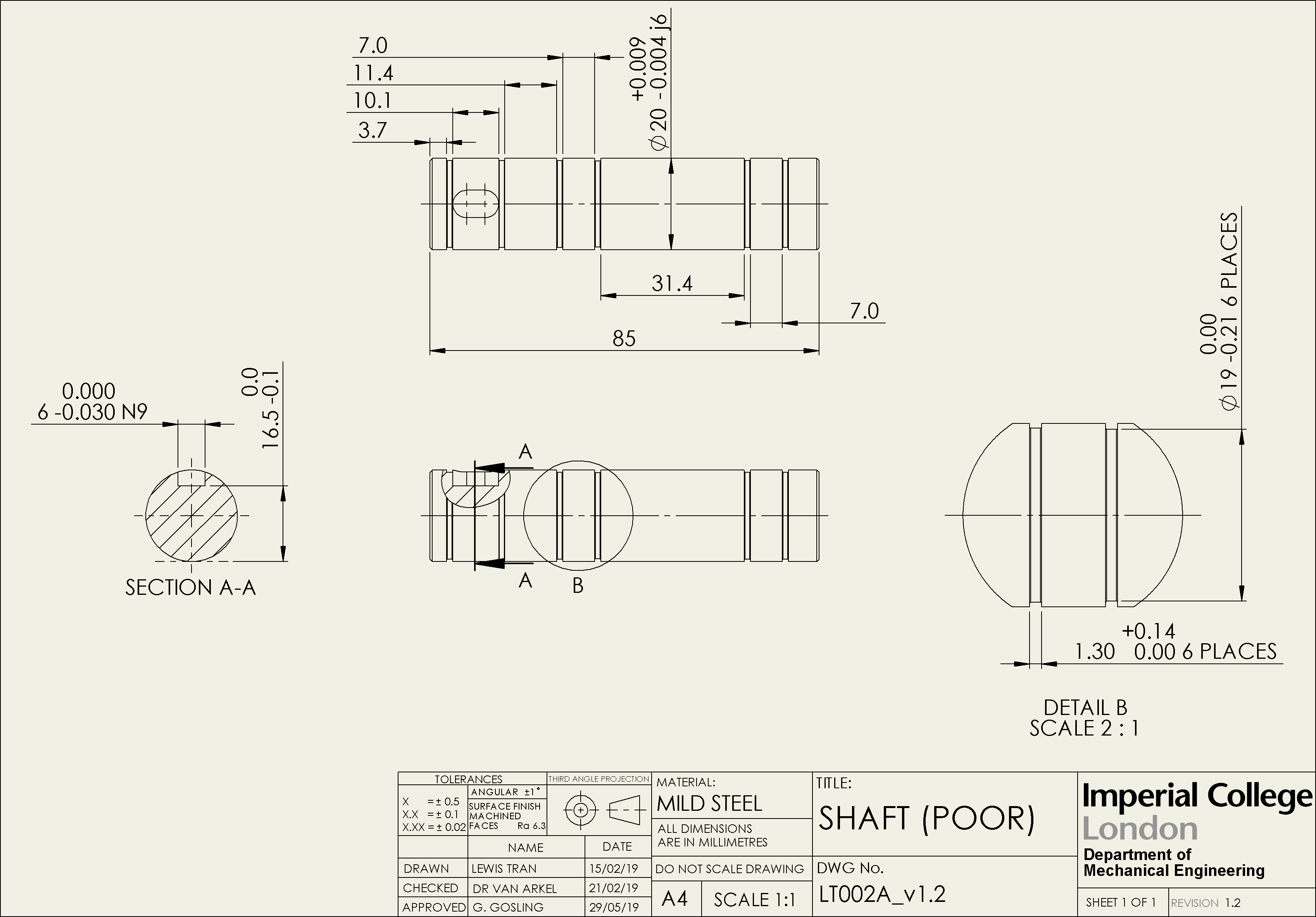
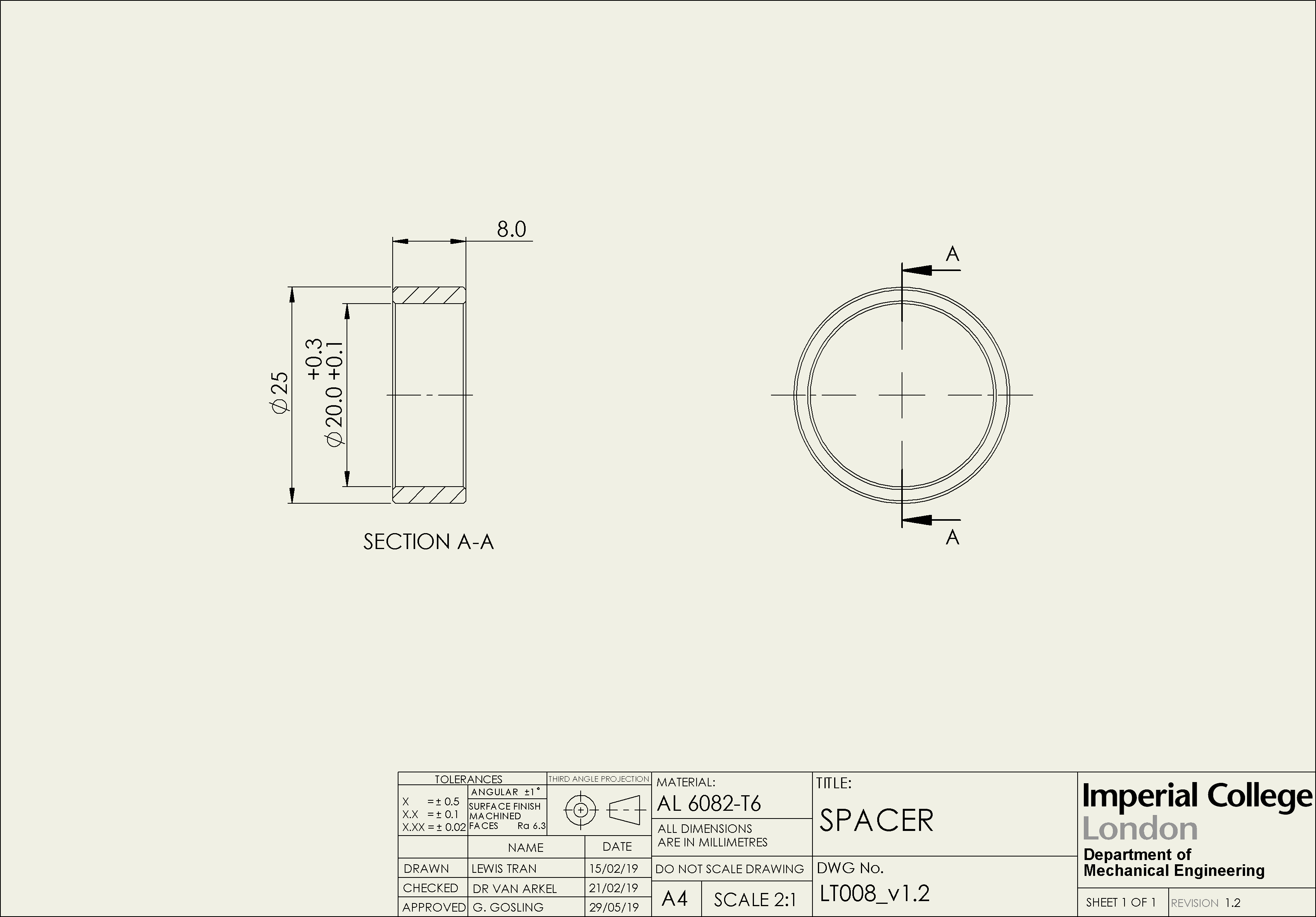
The example drawings provided demonstrate how the form of a shaft can contribute to the tolerance stack-up. The well designed shaft uses various constraint types to locate the bearings and fix the spur gear, including a spacer that seperates the two. The poorly designed shaft only uses external circlips that are referenced from a datum point.
The tear-shaped buttons can be used to change the reference point of certain dimensions. These changes will be reflected in the distribution model simulation.
Discussion points
- Try changing the datum reference point (A and B) to see how it affects the axial misalignment.
- Which shaft design is easier to manufacture and why?
- What is the benefit of using a spacer?
- Well Designed Housing
- Poorly Designed Housing
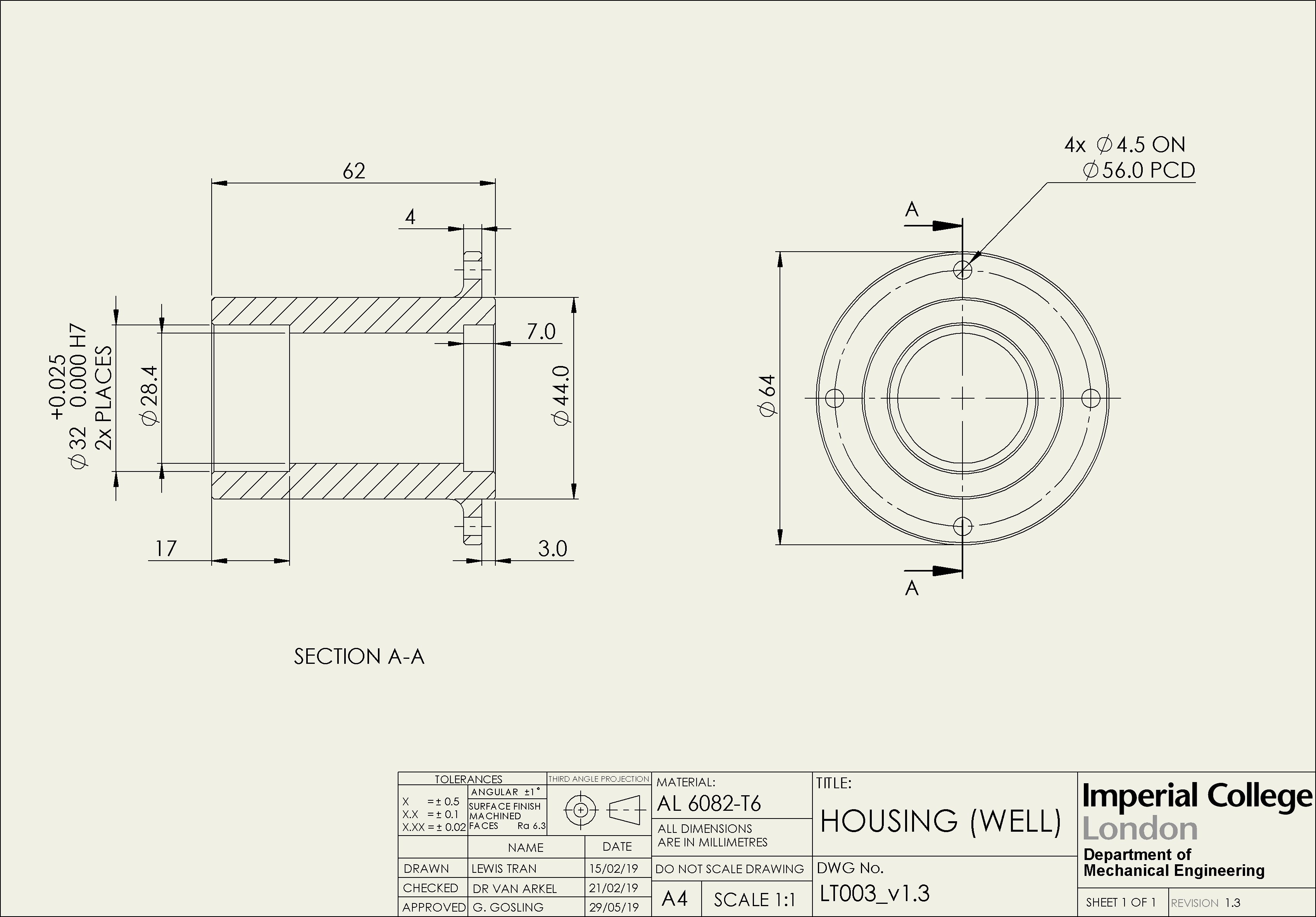
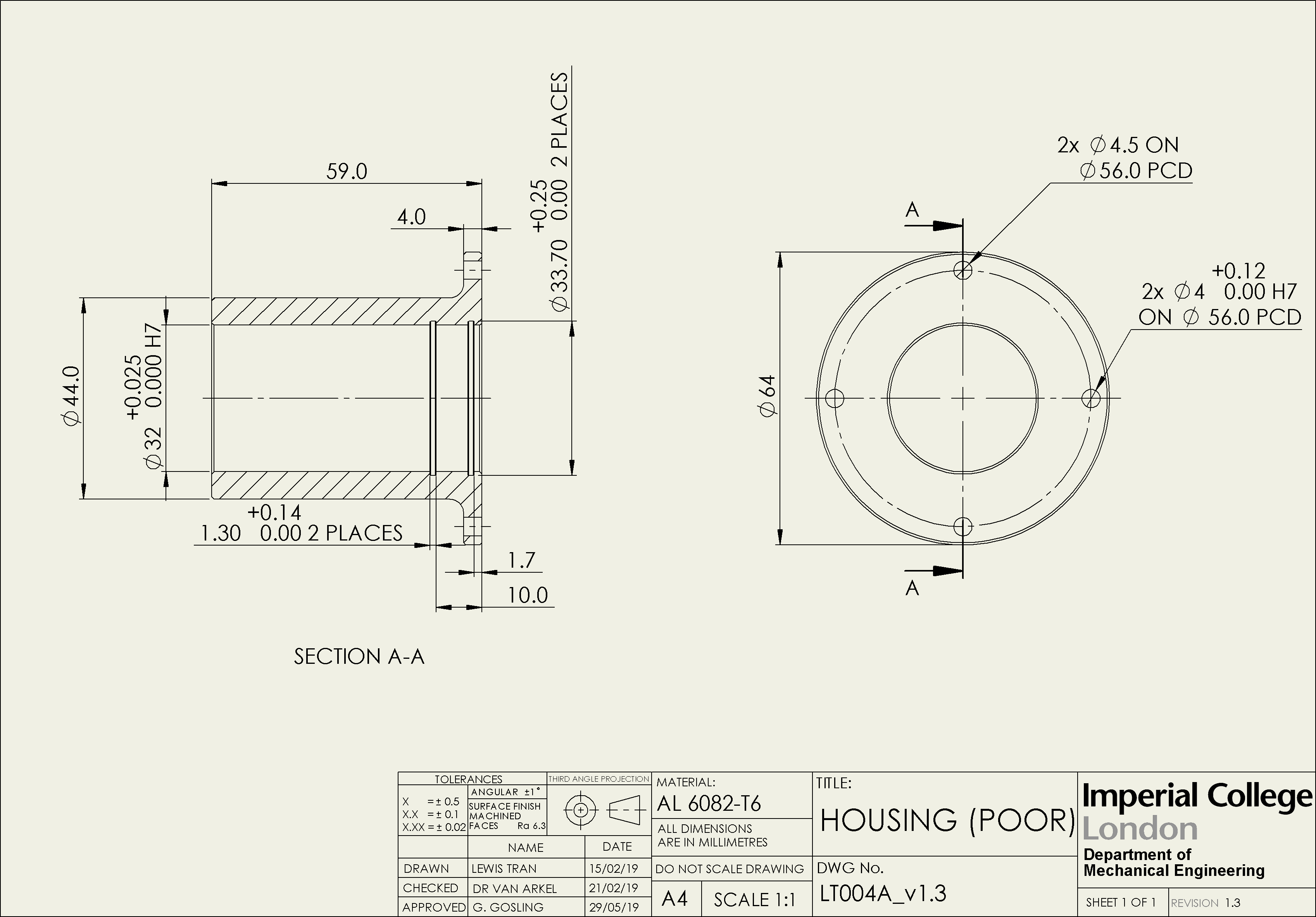
The design of the bearing housings also contribute to the tolerance stack-up in both the axial and radial directions. The well designed housing uses a combination of shoulders and an endcap to locate the fixed bearing and the plate. The poorly designed housing only uses internal circlips to locate the bearing, and fasteners to locate the plate.
The tear-shaped buttons can be used to change the type of fasteners on the poorly designed housing. These changes will be reflected in the distribution model simulation.
Discussion points
- Try comparing the radial stack-up contributions for the well designed and poorly designed housings.
- How is the tolerance stack-up affected by switching the type of fastener in the poorly designed housing - A is constrained by two dowel pins, B is constrained by two hex bolts.
The gear mechanism example, shown in Figure 4, is simulated in the Distribution Model to demonstrate the effect of tolerance stack-up on the misalignment of key components. Try comparing the results of the well designed and poorly designed drawings. How does the design of the components affect the misalignment and what improvements could be made?
- Distribution Model
- Assumptions
- Custom Distribution Model
| Mean (μm) | Standard Deviation (μm) | Rejected Units | |
|---|---|---|---|
| Well Designed | |||
| Poorly Designed |
This model simulates the stack-up distribution based on limits given in the engineering drawings. To test the variation in misalignment, select a direction, the number of units you wish to simulate and press run.
Datums and Fasteners Selected:
- Well designed shaft - Datum A.
- Poorly designed shaft - Datum A.
- Poorly designed housing - Pin Fasteners.
Quality Control:
- Reject units with a total axial misalignment greater than ± 0.1mm.
- Reject units with a total radial misalignment greater than ± 0.05mm.
Misalignment Direction:
Number of Units:
The distribution model simulates the misalignment of the gear mechanism based on the following assumptions:.
Tolerance asusmptions
The gear mechanism used in this example includes multiple components, each with their own unique tolerances. To simplify this model, only the custom manufactured parts (shown in the engineering drawings) were considered. The inherent tolerances of stock components (eg. bearings, bolts, gears) were not included as part of this simulation.
Model assumptions
The distribution model simulates the variation in part size using a Gaussian distribution, mapped across the upper and lower tolerance limits. Sizes are generated using an Irwin-Hall distribution that approximates a normal distribution without the need for excessive computation [1].
| Mean (μm) | Standard Deviation (μm) | Rejected Units | |
|---|---|---|---|
| Tolerance Set 1 | |||
| Tolerance Set 2 |
To simulate the distribution model for your own drawings, add the lower and upper bounds of each dimension under Tolerance Set 1, select the number of units and press run. To compare the distribution against another drawing design, add a second set of bounds under Tolerance Set 2.
Tolerance Set 1:
Tolerance Set 2:
Quality Control:
Number of Units:
Settings
To change which dimensions are displayed on each drawing, please select from the options below:
Toggle display:
- All - All dimensions relevant to manufacture are shown.
- Axial - Only the dimensions that contribute to the axial stack-up are shown.
- Radial - Only the dimensions that contribute to the radial stack-up are shown.
Learning Objects Beta
Thank you for testing the Learning Objects Beta. Please remember to leave feedback on your experience by pressing the Feedback link in the sidebar.
If you have any additional comments, or wish to report a bug, feel free to send an email at lt2415@ic.ac.uk.